Introduction
Now when the trilateration project is well on its way, I needed to rest my ears for a while, since those sound localization experiments makes a lot of noise!
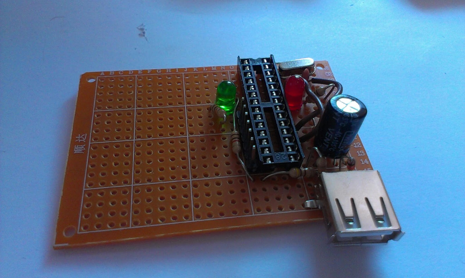
The trilateration aims to localize my robot in the room, giving it a coordinate position, but in order to create a map of the room I also need to know the robots orientation. To achieve that I ordered a electronic compass Circuit based on the HMC5883L chip. The HMC5883L is a "Three Axis Magnetic Field / Electronic Compass Sensor"
"The Honeywell HMC5883L is a surface-mount, multi-chip module designed for
low-field magnetic sensing with a digital interface for applications such as lowcost compassing and magnetometry" - datasheet
 |
| pinout |
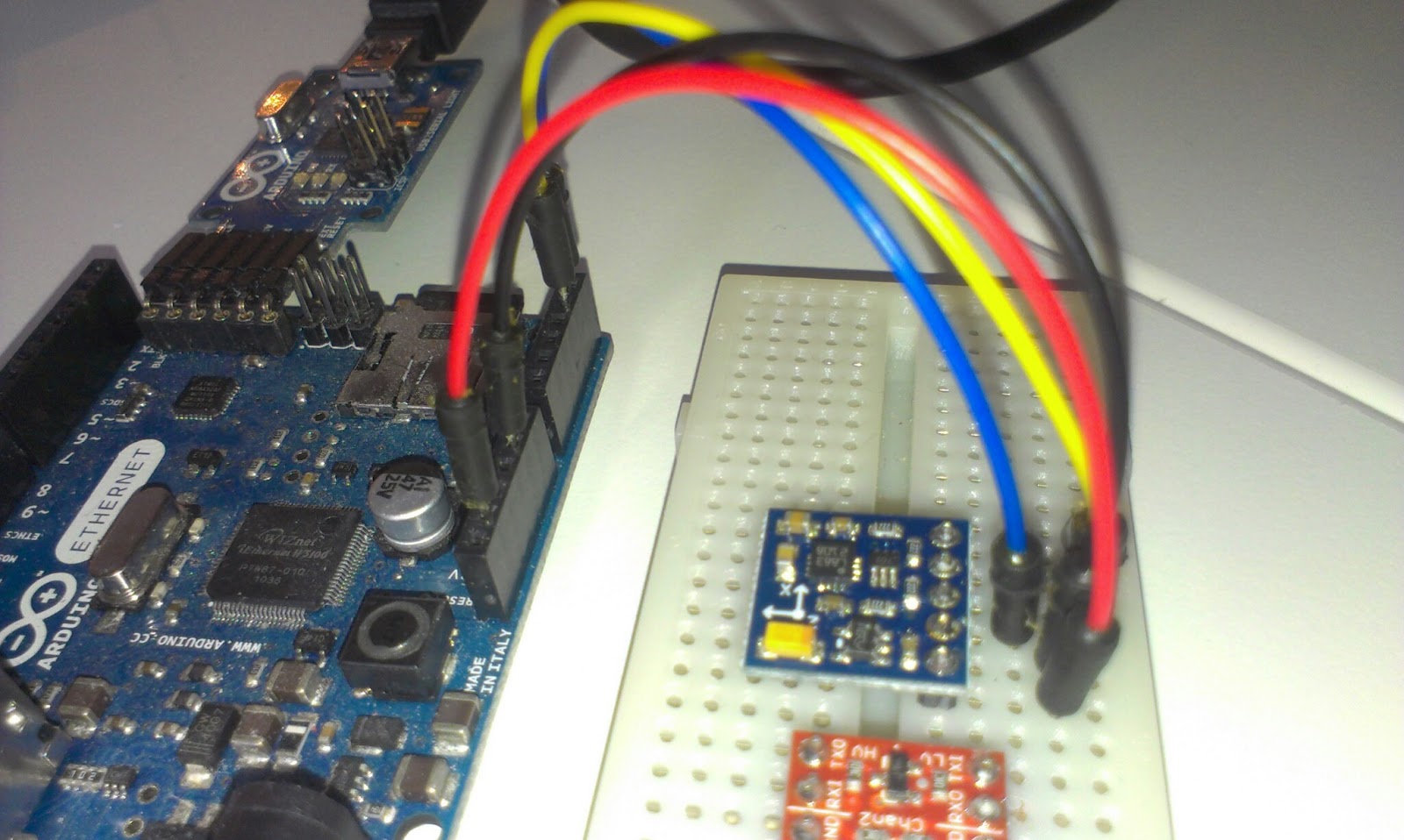
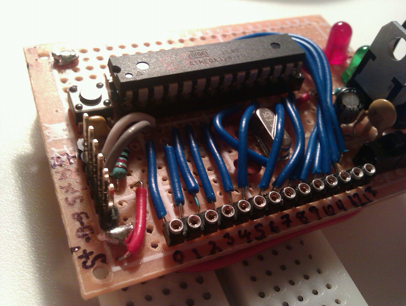
I connected it to my Arduino Ethernet
- VCC to 3.3V on the Arduino
- GND to GND on the Arduino
- SCL to A5 on the Arduino
- SCA to A4 on the Arduino
- DRDY was not connected (it is used to interrupt)
I found a
library and a
tutorial but in Arduino IDE 1.0.3 the names for some methods in the Wire library had changed so I changed the Wire.send() to Wire.write() and Wire.receive() to Wire.read() in the library.
 |
| connected |
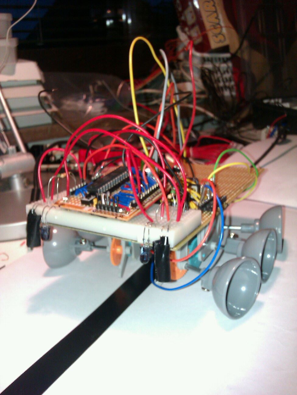
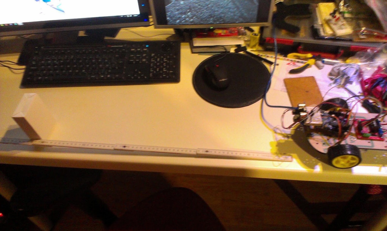
Experimental Setup
The Library contains an example and I ran it as it was, it outputs the direction in degrees. Something did not quite add up so I decided to draw the directions on a paper with 45 degree increments.
Results
 |
| Every line is a 45 degree output increment. It seems the angles calculated by the examples is not linearly divided on the circle... |
I have no graduated arc but it is quite clear something is wrong.
The first 180 degrees are more like 110 degrees. It is quite repeatable so I get almost the same measurements every-time, some noise.
Interpretation
This is my first 3D compass so my first guess was that the magnetometer is slightly misplaced or angled on the PCB.
There was also a little bit of measurement error on my behalf, since I moved the paper a few times, but should not be more than a few degrees and not such large errors.
Apparently this kind of error has been encountered before:
http://arduino.cc/forum/index.php?topic=100672.0
And I found a tutorial to help
https://www.loveelectronics.co.uk/Tutorials/13/tilt-compensated-compass-arduino-tutorial
They say that the IC should be tilted to work correctly... hm... and combined with a accelerometer, but why? I only intend to use it flat and not to tilt it in any direction...
I guess the earths magnetic field is tilted somehow and I need to compensate for that.
This blogger has similar problem but on another sensor, I must be missing something
http://www.varesano.net/blog/fabio/first-steps-hmc5843-arduino-verify-accuracy-its-results
If I want to use this as a compass it needs to be calibrated and compensated for the error.
Calibration discussion for another chip
http://arduino.cc/forum/index.php/topic,38104.0.html
And some code from
David W. Schultz
http://home.earthlink.net/~david.schultz/rnd/tracker/cal.c
Really good discussion on the sparkfun forum.
https://forum.sparkfun.com/viewtopic.php?f=14&t=18510&start=45
From that I started on a calibration method that calculates the minimum and maximum X and Y values (in Gauss) and re-centers the measurements using the map function. So before you measure anything you turn the robot around. Make sure you do not lift it and tilt it!
if (raw.XAxis < minX && raw.XAxis > -1000) {
minX = raw.XAxis;
}
if (raw.YAxis < minY && raw.YAxis > -1000) {
minY = raw.YAxis;
}
if (raw.XAxis > maxX && raw.XAxis < 1000) {
maxX = raw.XAxis;
}
if (raw.YAxis > maxY && raw.YAxis < 1000) {
maxY = raw.YAxis;
}
//recenter
float rX = map(raw.XAxis, minX, maxX, -255, 255);
float rY = map(raw.YAxis, minY, maxY, -255, 255);
// Calculate heading when the magnetometer is level, then correct for signs of axis.
// float heading = atan2(raw.YAxis, raw.XAxis);
float heading = atan2(rY, rX);
This gives very much better results slightly skewed angles but so much better...
 |
| Two measurements, still skewed... but better... |
To be continued...
Links:
Datasheet:
http://www51.honeywell.com/aero/common/documents/myaerospacecatalog-documents/Defense_Brochures-documents/HMC5883L_3-Axis_Digital_Compass_IC.pdf
dx.com
http://dx.com/p/three-axis-magnetic-field-electronic-compass-sensor-module-for-arduino-148734
Tutorial
https://www.loveelectronics.co.uk/Tutorials/8/hmc5883l-tutorial-and-arduino-library
My declination according to
http://magnetic-declination.com/ 4° 15' EAST
http://www.wolframalpha.com/input/?i=%284%C2%B0+15%27%29+in+radians gives me 74.18milliradians


