 |
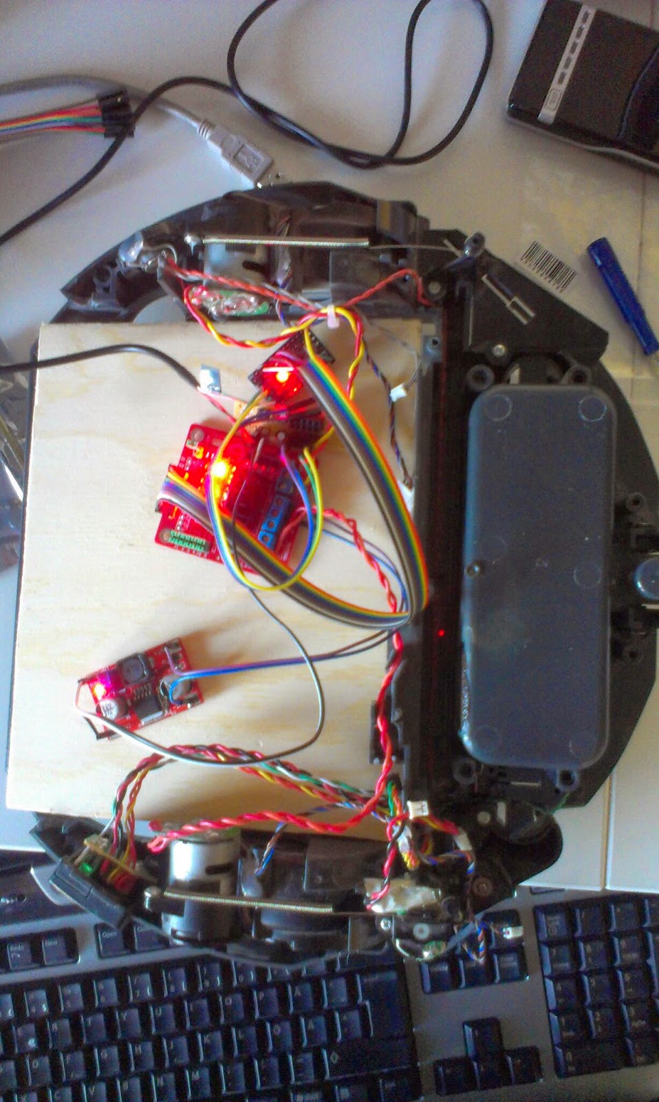
| Testing the motordriver and step-up power converter |
Sunday, March 30, 2014
Thursday, March 20, 2014
Parts for floorvac robot platform
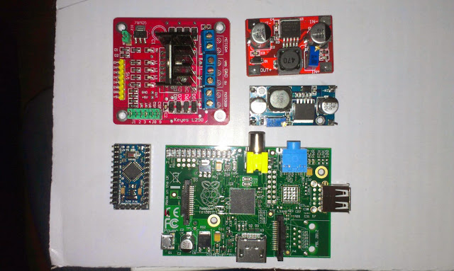 |
| New step up converter and motor driver arrived today... Here seen together with a rpi, mini arduino board. These components will be placed on the old Roomba robotic floorvac that I intend to replace the current robot platform with. |
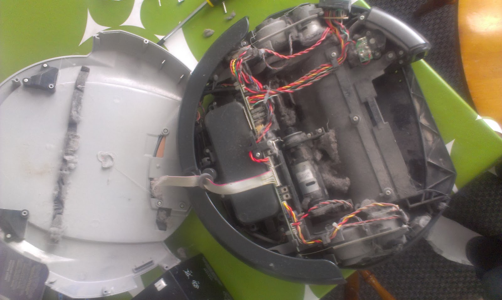 |
| The Roomba floorvac, dirty broken robot vacumcleaner... |
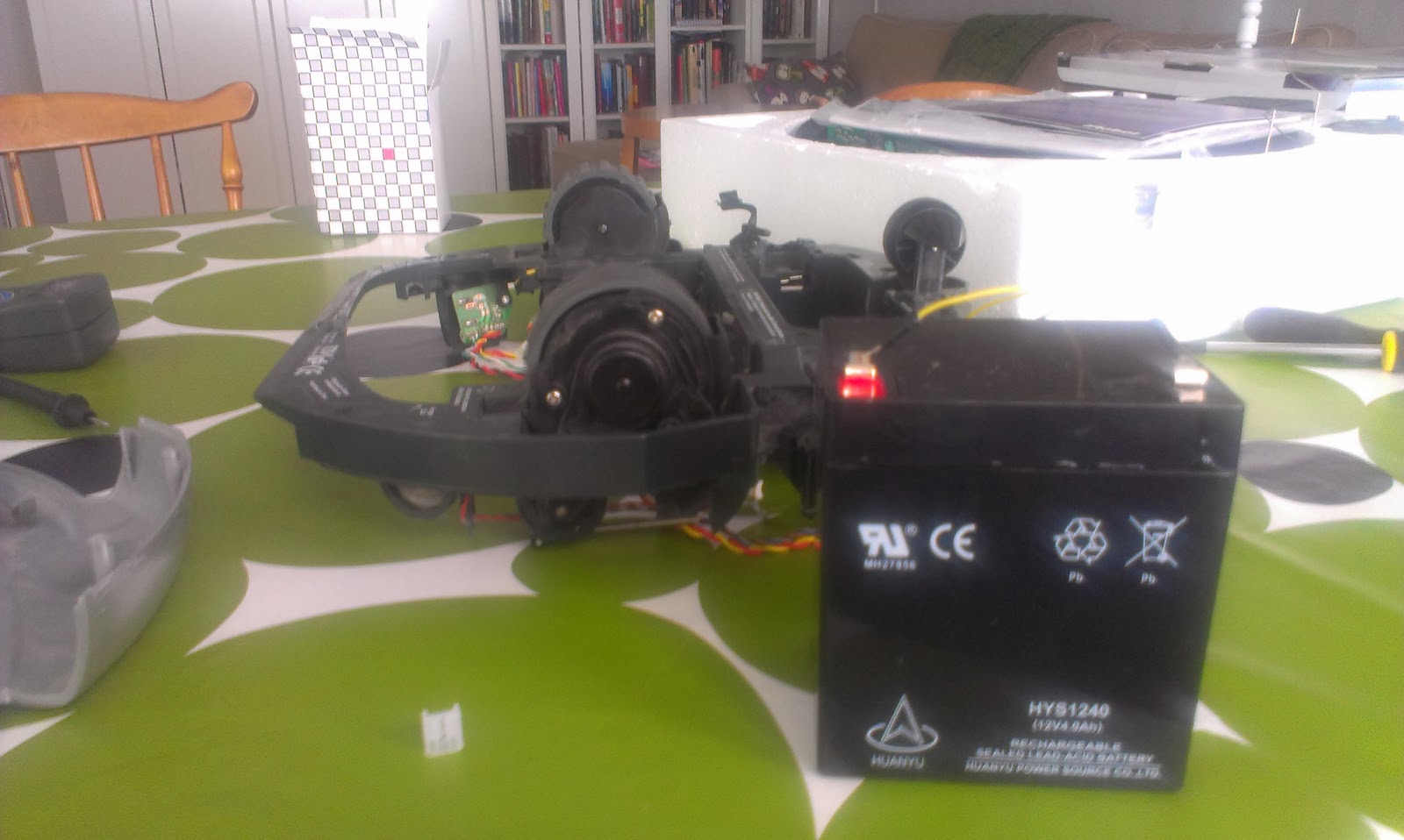 |
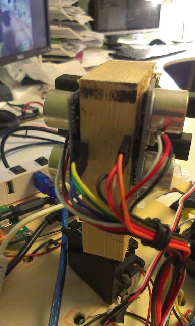
| Most components removed and testing the motors with 12V battery |
Tuesday, March 11, 2014
TFT01-2.2SP 2.2 SPI 240 x 320 TFT LCD Module
 |
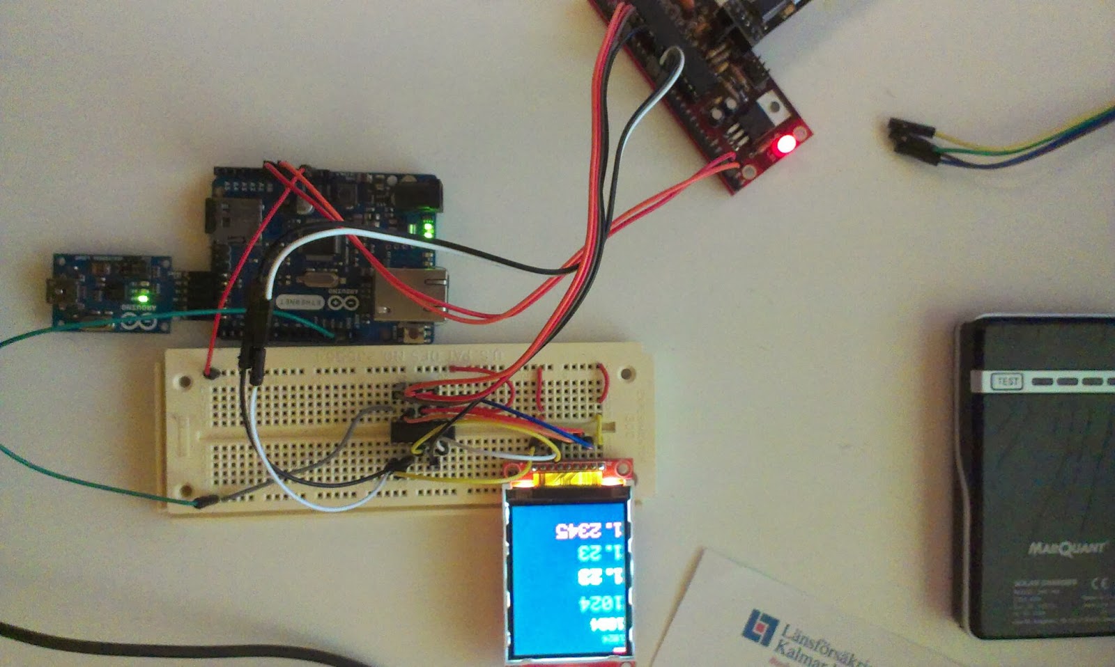
| The TFT connected to an arduino through an 4050B, the arduino ethernet is just there for its 3.3V |
With the library found on arduino forum it works...
I intend to connect this to a Raspberry pi later on together with a joystick and some buttons to create a robot remote control.
Links
Dx product pageLibrary download http://forum.arduino.cc/index.php?PHPSESSID=gmdo3f9gc28d8v4amun017ljk5&action=dlattach;topic=181679.0;attach=55282
Found here: http://forum.arduino.cc/index.php?topic=181679.15
4050B Datasheet here
Pin connections
D5 : CS
D4 : RESET
D6 : D/C
D11 : MOSI
D13 : SCK
D7 : LED
D12 : MISO
Monday, March 3, 2014
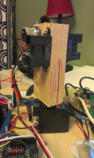
Testing the new GP2Y0A710K0F sensors
I just received two GP2Y0A710K0F sensors. These are a bit more expensive and has a range from 100 to 500cm. They will work together with the smaller pair of GP2Y0A02YK0F that I have on the robot right now. The smaller sensor has a range from 16 cm to 150 cm (or roughly 180 cm).
Since my plan is to use these for indoor mapping the combined long range and short range sensors will provide 16-500 cm range measurements.
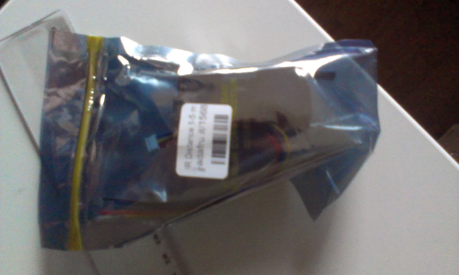 |
| New sensors packaged with a 220uF cap and cable |
The sensors are pretty noisy and comes with a 220uF electrolytic capacitor.
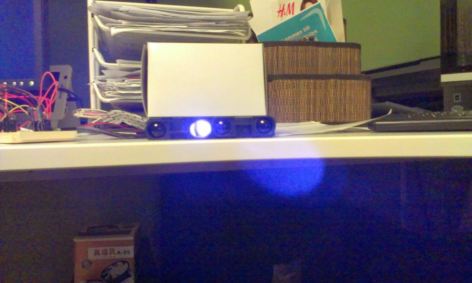 |
| The IR light is only visible on camera... seems really strong... |
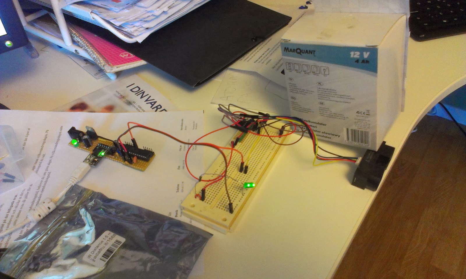 |
| Test setup with one sensor... |
 |
| The sensor is going to replace the ultrasonic sensor for long range measurements. |
 |
| The SLAM software, simulated data from bitmap data. To the left map generated from several measurements, red dot is best estimated position, to the right simulated input from the latest measurement. |
The Arduino test-sketch to test the two sensors...
void setup() {
  Serial.begin(9600);
}


void measure(int analogPin) {

  //remove analog lag
  analogRead(analogPin);

  int sensorValue = analogRead(analogPin);

  float voltage = 5.0f * (float)sensorValue / 1024.0f;

  Serial.print("Analog pin ");
  Serial.print(analogPin);
  Serial.print(" : ");
  Serial.println(voltage);
}

void loop() {
  measure(A0);
  measure(A1);
  delay(1000);
}
Saturday, February 15, 2014
Raspberry LCD-5110 Shield notes
My LCD-shield for raspberry pi is finally starting to show some promise.
I used the High-Low Tech tutorial for bootloading the attiny85.
I must not program the attiny when it is attached to the RPi since the programmer provides dangerous 4.8V to the 3.3 rails. And I also need to remove the LCD when I program it.
I intend to communicate with serial to the attiny from the pi.
http://www.instructables.com/id/Easy-ATTiny-Serial-Communication-with-Tiny-AVR-Pro/
This contains instructions on how to use the pi's serial port
http://wyolum.com/projects/alamode/
http://raspberrypihobbyist.blogspot.se/2012/08/raspberry-pi-serial-port.html
http://www.hobbytronics.co.uk/raspberry-pi-serial-port
I run minicom to communicate with my program...
Right now I remove the shield and LCD from the shield, connect the programmer, run arduino as sudo, write my changes and then removes the programmer, attach shield to rpi, bootup rpi and login through ssh, connect to shield through minicom to find some minor error... phew...shut down pi, start over...
 |
| Nokia 5110 on rpi shield made out of Arduino shield protoboard, featuring some buttons, leds and a Attiny85 |
The Attiny85
On the shield I placed one attiny85 to use as analog to digital converter. It is placed on the little surface mount area and is programmed using the ICSP header next to it. I connected the SCK, MISO and MOSI to 13,12, 11 on the arduino shield. The reset is connected to the reset button.I used the High-Low Tech tutorial for bootloading the attiny85.
I must not program the attiny when it is attached to the RPi since the programmer provides dangerous 4.8V to the 3.3 rails. And I also need to remove the LCD when I program it.
I intend to communicate with serial to the attiny from the pi.
http://www.instructables.com/id/Easy-ATTiny-Serial-Communication-with-Tiny-AVR-Pro/
This contains instructions on how to use the pi's serial port
http://wyolum.com/projects/alamode/
http://raspberrypihobbyist.blogspot.se/2012/08/raspberry-pi-serial-port.html
http://www.hobbytronics.co.uk/raspberry-pi-serial-port
I run minicom to communicate with my program...
minicom -b 9600 -o -D /dev/ttyAMA0The current programming approach is quite painful so I think I will need to rethink it. maybe its time to get a 3.3V programmer or levelconvert the programmers signal?
Right now I remove the shield and LCD from the shield, connect the programmer, run arduino as sudo, write my changes and then removes the programmer, attach shield to rpi, bootup rpi and login through ssh, connect to shield through minicom to find some minor error... phew...shut down pi, start over...
Friday, February 7, 2014
More work on the headless RPi with LCD and buttons
I intend to run my RPi headless, here is a collection of good resources so I can find them again...
To build and interact with buttons...
https://www.cl.cam.ac.uk/projects/raspberrypi/tutorials/robot/buttons_and_switches/
Run scripts on startup and shutdown, not sure if they mixup /etc/rc0.d with /etc/rc6.d
http://en.kioskea.net/faq/3348-ubuntu-executing-a-script-at-startup-and-shutdown
Spawn subprocesses in python and interact with them
http://docs.python.org/2/library/subprocess.html#module-subprocess
 |
| I added a button to the circuit... |
Thursday, February 6, 2014
Screen for the robot
My robot contains a Raspberry Pi model A. Right now I always ssh into it in order to start the robot application and I need to remotely ssh all commands.
I intend to create a simple userinterface in the form of a LCD and a few buttons to make it easier to turn on and off and perhaps reboot and reload the applications.
I have a 5110 that I have used together with arduino boards before.
I found this tutorial: https://github.com/XavierBerger/pcd8544
This is built using wiringPi
http://wiringpi.com/download-and-install/

The tutorial did not work fully, apparently I need wiringpi2, since I get the message "ImportError: No module named wiringpi2"
http://raspi.tv/how-to-install-wiringpi2-for-python-on-the-raspberry-pi#install
"sudo pip install wiringpi2"
Worked the second time...
I intend to create a simple userinterface in the form of a LCD and a few buttons to make it easier to turn on and off and perhaps reboot and reload the applications.
I have a 5110 that I have used together with arduino boards before.
I found this tutorial: https://github.com/XavierBerger/pcd8544
This is built using wiringPi
http://wiringpi.com/download-and-install/
The tutorial did not work fully, apparently I need wiringpi2, since I get the message "ImportError: No module named wiringpi2"
http://raspi.tv/how-to-install-wiringpi2-for-python-on-the-raspberry-pi#install
"sudo pip install wiringpi2"
Worked the second time...
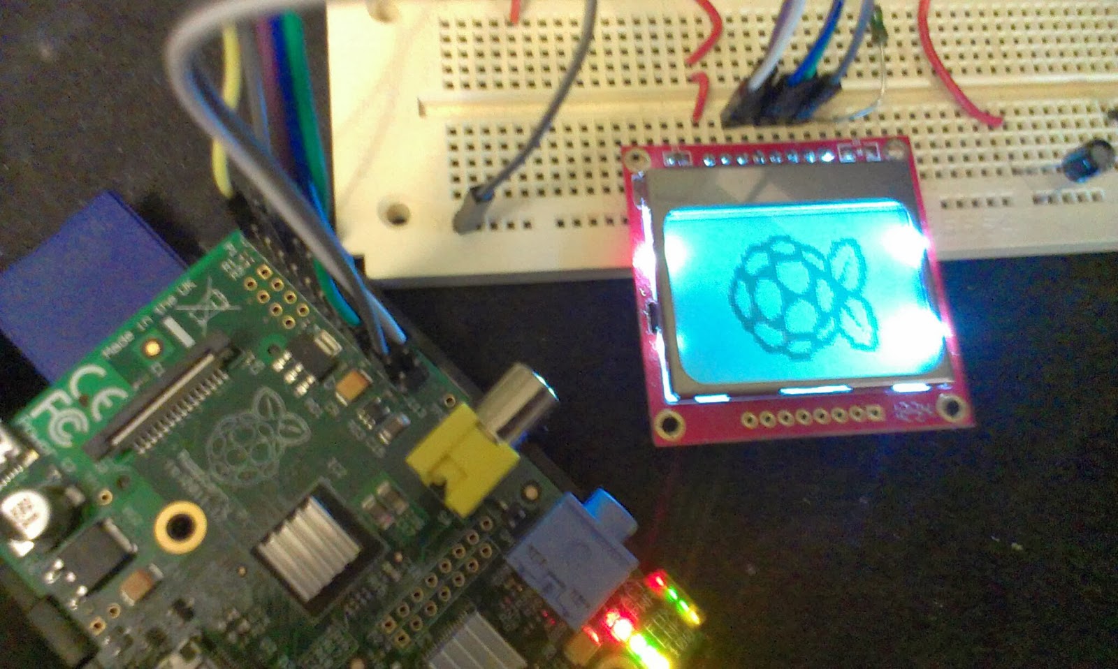 |
| Yay... |
Tuesday, January 21, 2014
New servo for robot head
Problem: The old servo is not strong enough to turn the robots head when there is a lot of cables attached to the head.
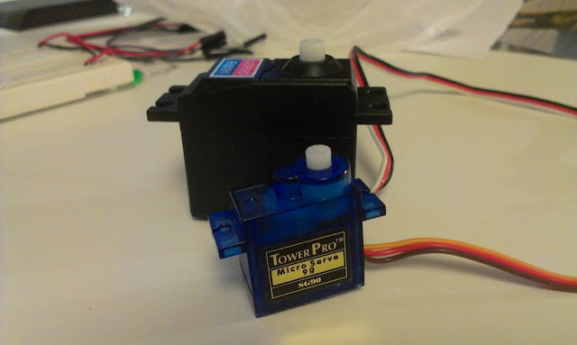 |
| I bought a new larger servo yesterday, the black large one in the background should provide much more power than the old blue micro servo I used before. |
Solution: Buy new stronger servo.
 |
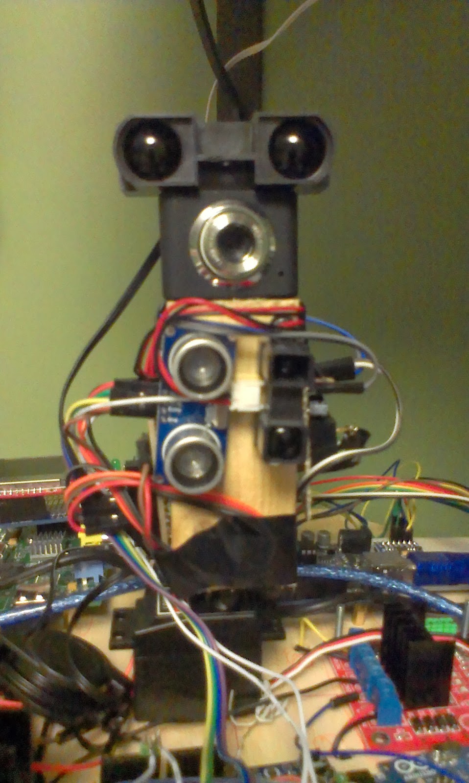
| The servo should turn the robots head so that distance sensors can make measurements in all directions, problem was that the old servo was not strong enough to turn the head with the resistance of the cables. |
New problem: new servo creates a lot of electrical disturbance.
Solution: Add more and bigger caps!
 |
| There is a lot of cables coming out of the sensors (4+4+3+3) making the head a lot heavier to turn. |
All those cables makes the head difficult to work with, I think I need to make a custom Arduino board and attach it to the head.
Subscribe to:
Posts (Atom)